

Precision Tube Fitting Flange Connectors by Samvay Fluid Tekniks Inc.
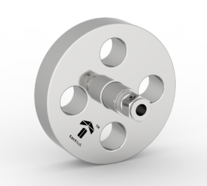
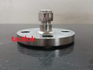
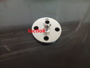
Connect tubing to flanged equipment seamlessly with Samvay Fluid Tekniks Inc.’s specialized Flange Connectors featuring double compression tube fittings on one side. These hybrid connectors combine the security of ASME B16.5 flanges with the reliability of industrial double compression tube fittings, creating the perfect solution for instrumentation, hydraulic, and process connections where tubing must interface with flanged equipment.
Product Overview
Flange connectors with double compression tube fittings serve as critical transition points between tube runs and flanged equipment such as valves, pumps, instruments, and pressure vessels. One end features a standard ASME B16.5 flange for bolted connections, while the other end incorporates a precision-engineered double compression tube fitting for secure tube attachment.
Why These Connectors Are Essential:
| Application | Challenge | Solution |
|---|---|---|
| Instrument Connections | Connect tubing to flanged transmitters | Flange connector with tube fitting |
| Hydraulic Systems | Tube to valve manifold connections | Leak-free double compression seal |
| Sample Lines | Connect to flanged process equipment | Reliable, removable connection |
| Panel Interfaces | Tube through-panel to flanged equipment | Compact, space-saving design |
| Field Modifications | Adding instruments to existing flanged systems | Easy retrofit without pipe welding |
Double Compression Tube Fitting Advantages:
| Feature | Benefit |
|---|---|
| Two Ferrule System | Front ferrule seals, back ferrule grips – independent functions |
| No Tube Rotation | Prevents scoring, ideal for vibration |
| Reusable | Multiple remakes without performance loss |
| Vibration Resistant | Back ferrule grips securely, absorbs movement |
| Wide Temperature Range | -425°F to 1200°F (-254°C to 649°C) |
| Leak-Free | Metal-to-metal seal, no elastomers |
Key Features & Benefits
| Feature | Technical Benefit | Operational Benefit |
|---|---|---|
| One-Piece Machined Body | No welds, no potential leak paths | Highest integrity, compact design |
| ASME B16.5 Flange End | Standard bolt pattern, facing | Interchangeable with all flanged equipment |
| Double Compression Tube End | Two-ferrule system for secure grip and seal | Reliable up to 6000 PSI |
| Full Material Traceability | EN 10204 3.1 certification | Audit-ready quality records |
| Multiple Facing Options | RF, RTJ, FF to match system | Perfect gasket compatibility |
| All Tube Sizes | 1/8″ to 1″ OD, metric sizes available | Universal application |
| All Pressure Classes | 150# to 2500# flanges | Any system pressure |
| Precision Machining | CNC turned for perfect concentricity | No misalignment, easy assembly |
Technical Specifications
Material of Construction
- Stainless Steel: SS304, SS316/L, SS316Ti, SS321
- Carbon Steel: ASTM A105 with SS316 tube fitting insert
- Duplex: UNS S31803
- Super Duplex: UNS S32750
- Nickel Alloys: Monel 400, Inconel 625, Hastelloy C276
Flange End Specifications
- Flange Standard: ASME B16.5 (standard); DIN EN 1092-1, JIS B2220 available
- Flange Size Range (NPS): 1/2″ to 4″ (larger sizes consult factory)
- Pressure Class: Class 150, 300, 600, 900, 1500, 2500
- Facing Types: Raised Face (RF), Ring Type Joint (RTJ), Flat Face (FF), Male/Female, Tongue & Groove
- Flange Face Finish: 125-250 μin Ra standard; 63 μin Ra for RTJ
Tube End Specifications
- Tube Fitting Type: Double compression (two ferrule) instrumentation fitting
- Tube Size Range: 1/8″, 1/4″, 3/8″, 1/2″, 5/8″, 3/4″, 1″ OD; Metric: 6mm – 25mm
- Tube Compatibility: Seamless stainless steel tubing, copper, Monel, Inconel, titanium
- Pressure Rating: Up to 6000 PSI (414 Bar) at ambient temperature
- Temperature Rating: -425°F to 1200°F (-254°C to 649°C) depending on material
- Ferrule Material: Same as body material (standard); Hardened available for difficult tubing
- Tube Insertion Depth: Positive stop for consistent assembly
Overall Specifications
- Manufacturing Process: Solid barstock, CNC machined in one piece
- Surface Finish: As-machined, passivated, electropolished
- Identification: Laser marked with size, material, pressure rating, heat code
- Testing: 100% pressure tested
- Certification: EN 10204 3.1 standard
Complete Product Range
By Flange Size & Tube Size Matrix:
| Flange Size (NPS) | Available Tube Sizes (OD) | Typical Applications |
|---|---|---|
| 1/2″ | 1/8″, 1/4″, 3/8″, 1/2″, 6mm, 8mm, 10mm, 12mm | Instrument connections, small bore |
| 3/4″ | 1/4″, 3/8″, 1/2″, 5/8″, 8mm, 10mm, 12mm, 14mm, 16mm | General instrumentation |
| 1″ | 1/2″, 5/8″, 3/4″, 12mm, 14mm, 16mm, 18mm, 20mm | Hydraulic systems |
| 1-1/2″ | 3/4″, 1″, 18mm, 20mm, 22mm, 25mm | Large bore, high flow |
| 2″ | 1″, 25mm, 32mm (special) | High capacity systems |
| 3″ | 1″ (multiple connections possible) | Manifold applications |
| 4″ | 1″ (multiple connections) | Distribution headers |
By Flange Pressure Class:
| Class | Tube End Pressure Rating | Typical Applications |
|---|---|---|
| Class 150 | 3000 PSI | Low-pressure systems, water, air |
| Class 300 | 3000-6000 PSI | Medium-pressure process |
| Class 600 | 6000 PSI | High-pressure systems |
| Class 900 | 6000 PSI | Very high-pressure, special |
| Class 1500 | 6000 PSI | Extreme pressure, critical |
| Class 2500 | 6000 PSI | Ultra-high pressure, wellhead |
By Flange Face Type:
| Face Type | Tube End | Typical Gasket | Application |
|---|---|---|---|
| Raised Face (RF) | Any tube size | Spiral wound, ring | General purpose |
| Ring Type Joint (RTJ) | Any tube size | Oval/octagonal ring | High-pressure, high-temp |
| Flat Face (FF) | Any tube size | Full face | Cast iron equipment |
| Male/Female | Any tube size | Confined | Toxic fluids |
| Tongue & Groove | Any tube size | Confined | Critical service |
By Material Combination:
| Body Material | Tube End Material | Application |
|---|---|---|
| SS316/L | SS316/L | General chemical, pharmaceutical, food |
| SS304/L | SS304/L | Water, air, general purpose |
| A105 CS | SS316/L (insert) | Economical, carbon steel flange with SS tube fitting |
| A105 CS | CS tube fitting | Carbon steel system |
| F11 / F22 | SS316/L | High temperature |
| Duplex 2205 | Duplex 2205 | Offshore, chloride service |
| Super Duplex | Super Duplex | Extreme corrosion, subsea |
| Monel 400 | Monel 400 | Hydrofluoric acid, seawater |
| Inconel 625 | Inconel 625 | High temperature, extreme corrosion |
| Hastelloy C276 | Hastelloy C276 | Extreme chemical resistance |
By Tube Fitting Configuration:
| Configuration | Description | Best For |
|---|---|---|
| Standard Double Compression | Two-ferrule system, most common | All general applications |
| Long Ferrule Set | Extended grip length | Thin wall tubing |
| Oxygen Service | Special cleaning, no lubricants | Oxygen systems |
| High Purity | Electropolished, special packaging | Pharmaceutical, semiconductor |
| Nuclear Grade | Full traceability, special testing | Nuclear applications |
Dimensional Information
Typical Dimensions (Reference Only – Consult Factory for Exact):
| Flange Size | Tube Size | Flange OD | Length (Face to Tube End) | Bolt Circle | Bolt Holes |
|---|---|---|---|---|---|
| 1/2″ Class 150 | 1/4″ tube | 3.50″ | 3.0″ | 2.38″ | 4 x 1/2″ |
| 1/2″ Class 300 | 1/4″ tube | 3.75″ | 3.2″ | 2.62″ | 4 x 5/8″ |
| 1/2″ Class 600 | 1/4″ tube | 3.75″ | 3.5″ | 2.62″ | 4 x 5/8″ |
| 3/4″ Class 150 | 1/2″ tube | 3.88″ | 3.2″ | 2.75″ | 4 x 1/2″ |
| 3/4″ Class 300 | 1/2″ tube | 4.62″ | 3.5″ | 3.25″ | 4 x 3/4″ |
| 1″ Class 150 | 1/2″ tube | 4.25″ | 3.5″ | 3.12″ | 4 x 1/2″ |
| 1″ Class 300 | 1/2″ tube | 4.88″ | 3.8″ | 3.50″ | 4 x 5/8″ |
| 1″ Class 600 | 1/2″ tube | 5.00″ | 4.0″ | 3.50″ | 4 x 3/4″ |
| 1-1/2″ Class 150 | 3/4″ tube | 5.00″ | 4.0″ | 3.88″ | 4 x 1/2″ |
| 1-1/2″ Class 300 | 3/4″ tube | 6.12″ | 4.5″ | 4.50″ | 4 x 3/4″ |
| 2″ Class 150 | 1″ tube | 6.00″ | 4.5″ | 4.75″ | 4 x 5/8″ |
| 2″ Class 300 | 1″ tube | 6.50″ | 5.0″ | 5.00″ | 8 x 5/8″ |
Note: Length varies with tube size and pressure class. Custom lengths available on request.
Double Compression Tube Fitting Details
How Double Compression Fittings Work: The two-ferrule system provides independent sealing and gripping functions:
| Component | Function |
|---|---|
| Front Ferrule | Seals on the tube and fitting body. Creates leak-tight metal-to-metal seal. |
| Back Ferrule | Grips the tube securely. Acts as a spring, absorbing vibration and preventing loosening. |
| Body | Precision machined with tapered seat. Provides consistent ferrule compression. |
| Nut | Drives ferrules during make-up. Captive design prevents ferrule loss. |
Assembly Sequence:
- Prepare Tube: Cut square, deburr inside and out
- Insert Tube: Through nut, through ferrules, bottom in body
- Hand Tighten: Turn nut until finger tight
- Mark Position: Mark nut at 6 o’clock position
- Final Tighten: Turn nut 1-1/4 turns (for 1/4″ to 1/2″ sizes) to 12 o’clock
- Check Assembly: Ferrules properly swaged, tube secure
Quality & Compliance
Material Quality
| Parameter | Standard / Test |
|---|---|
| Raw Material | Certified barstock from prime mills |
| Material Certification | EN 10204 3.1 Mill Test Certificate |
| Chemical Composition | Spectro analysis verification |
| Mechanical Properties | Tensile, yield, elongation testing |
| Hardness Testing | For NACE compliance |
| PMI Testing | Positive Material Identification (standard for alloys) |
| Grain Structure | Microstructure analysis for critical applications |
Dimensional Quality
| Parameter | Standard / Test |
|---|---|
| Flange Dimensions | ASME B16.5 gauges and fixtures |
| Tube Fitting Dimensions | Precision optical comparators |
| Thread Accuracy | ASME B1.20.1 (NPT) or ISO 228 (BSP) gauges |
| Concentricity | Flange bore to tube fitting centerline within 0.005″ TIR |
| Surface Finish | Ra 16 or better on sealing surfaces |
| Ferrule Geometry | 100% visual inspection |
Performance Testing
| Test | Method | Acceptance Criteria |
|---|---|---|
| Hydrostatic Test | 1.5x rated pressure | No leakage, no permanent deformation |
Certifications
| Certification | Applicability |
|---|---|
| ISO 9001:2015 | Quality management system |
| EN 10204 3.1 | Material traceability |
| ASME B16.5 | Flange design standard |
| ASME B31.1 / B31.3 | Piping codes |
| NACE MR0175 / ISO 15156 | Sour service (optional) |
| NACE MR0103 | Refinery sour service (optional) |
Installation Guidelines
Step-by-Step Installation
1. Prepare the Tube:
- Cut tube square using a tube cutter (not hacksaw)
- Remove all burrs inside and outside
- Clean tube end of oil, dirt, and debris
2. Prepare the Connector:
- Check that fitting is clean and undamaged
- Verify ferrule set is correct for tube size
- Ensure threads are clean
Assemble Tube to Connector:
- Slide nut onto tube, then ferrules (back ferrule first, then front ferrule)
- Insert tube into body until it bottoms against shoulder
- Hand tighten nut until snug
- Mark nut position
- Tighten to specified turns or torque
Flange Connection:
- Ensure flange face is clean and undamaged
- Position gasket correctly on flange face
- Align bolt holes with mating flange
- Insert bolts, hand tighten
- Tighten bolts in cross pattern to specified torque
Check Assembly:
- Verify tube is fully inserted (no gap)
- Verify ferrule swage is correct
- Pressure test system before operation
Common Mistakes to Avoid
| Mistake | Consequence | Prevention |
|---|---|---|
| Tube not fully inserted | Ferrule grips incomplete, leakage | Push until bottom, mark depth |
| Overtightening tube nut | Ferrule damage, tube deformation | Use prescribed turns/torque |
| Undertightening tube nut | Incomplete swage, leakage | Use prescribed turns/torque |
| Wrong ferrule orientation | No seal, no grip | Back ferrule first, then front |
| Damaged ferrule | Leakage, replacement needed | Inspect before assembly |
| Dirty tube | Ferrule slips, seal fails | Clean tube thoroughly |
| Incorrect gasket | Flange leakage | Use correct gasket type/material |
| Uneven bolt tightening | Flange distortion, leakage | Cross-tighten in sequence |
Selection Guide
By Application
| Application | Flange Class | Tube Size | Material | Special Features |
|---|---|---|---|---|
| Instrument Connection to Vessel | 150# or 300# | 1/4″ or 1/2″ | SS316 | RF face, standard |
| Pressure Transmitter to Flanged Nozzle | 150# – 600# | 1/4″ or 1/2″ | SS316 | RF or RTJ |
| Hydraulic Pump to Valve Manifold | 300# – 600# | 1/2″ or 3/4″ | SS316 | High-pressure rated |
| Sample Cooler Connections | 150# – 300# | 1/4″ or 3/8″ | SS316 | Compact design |
| Chemical Injection Quills | 300# – 1500# | 1/4″ or 3/8″ | Hastelloy | Corrosion resistant |
| Offshore Hydraulics | 600# – 1500# | 1/2″ or 3/4″ | Duplex | NACE, saltwater resistant |
| Oxygen Systems | 300# | 1/4″ or 1/2″ | SS316 | Oxygen cleaning |
| High Purity Systems | 150# | 1/4″ or 1/2″ | SS316L | Electropolished |
By Pressure
| System Pressure | Recommended Flange Class | Tube Fitting Rating |
|---|---|---|
| 0-285 PSI | Class 150 | 3000+ PSI (ample margin) |
| 285-740 PSI | Class 300 | 3000+ PSI |
| 740-1480 PSI | Class 600 | 3000-6000 PSI |
| 1480-2220 PSI | Class 900 | 6000 PSI |
| 2220-3705 PSI | Class 1500 | 6000 PSI |
| 3705-6170 PSI | Class 2500 | 6000 PSI |
By Tube Size
| Tube OD | Common Applications | Available Flange Sizes |
|---|---|---|
| 1/8″ | Small instrumentation | 1/2″ only |
| 1/4″ | General instrumentation | 1/2″, 3/4″ |
| 3/8″ | General purpose | 1/2″, 3/4″, 1″ |
| 1/2″ | Hydraulics, process | 3/4″, 1″, 1-1/2″ |
| 3/4″ | Large bore systems | 1″, 1-1/2″, 2″ |
| 1″ | High flow systems | 1-1/2″, 2″, 3″ |
Industry Applications
Oil & Gas
| Application | Flange-Tube Combo | Material | Special Requirements |
|---|---|---|---|
| Wellhead Control Panels | 1/2″ Class 600 to 1/4″ tube | SS316 | NACE MR0175 |
| Flow Computer Connections | 1/2″ Class 300 to 1/4″ tube | SS316 | Intrinsically safe |
| Chemical Injection Skids | 1/2″ Class 1500 to 1/4″ tube | SS316/Hastelloy | High-pressure, corrosion |
| Offshore Hydraulics | 3/4″ Class 1500 to 1/2″ tube | Duplex | Saltwater resistant |
| Refinery Instrumentation | 1/2″ Class 300 to 1/4″ tube | SS316 | Fire-safe |
Chemical Processing
| Application | Flange-Tube Combo | Material | Special Requirements |
|---|---|---|---|
| Reactor Instrumentation | 1/2″ Class 300 to 1/4″ tube | SS316/Hastelloy | Chemical resistant |
| Acid Lines | 1/2″ Class 150 to 1/4″ tube | Hastelloy | Corrosion resistant |
| Solvent Transfer | 3/4″ Class 300 to 1/2″ tube | SS316 | Standard |
| Batch Reactors | 1/2″ Class 150 to 1/4″ tube | SS316 | Easy disconnect |
Power Generation
| Application | Flange-Tube Combo | Material | Special Requirements |
|---|---|---|---|
| Boiler Instrumentation | 1/2″ Class 600 to 1/4″ tube | SS316 | High-temperature |
| Turbine Controls | 1/2″ Class 300 to 1/4″ tube | SS316 | Vibration resistant |
| Feedwater Systems | 3/4″ Class 900 to 1/2″ tube | SS316 | High-pressure |
| Cooling Water | 1″ Class 150 to 3/4″ tube | SS304 | General purpose |
Pharmaceutical / Biotech
| Application | Flange-Tube Combo | Material | Special Requirements |
|---|---|---|---|
| WFI Systems | 1/2″ Class 150 to 1/4″ tube | SS316L | Electropolished, Ra<0.4μm |
| Bioreactor Connections | 1/2″ Class 150 to 1/4″ tube | SS316L | Sanitary, drainable |
| Clean Steam | 1/2″ Class 300 to 1/4″ tube | SS316L | High-purity |
| Buffer Preparation | 3/4″ Class 150 to 1/2″ tube | SS316L | Electropolished |
Food & Beverage
| Application | Flange-Tube Combo | Material | Special Requirements |
|---|---|---|---|
| Processing Lines | 1/2″ Class 150 to 1/4″ tube | SS316 | Food-grade |
| CIP Systems | 3/4″ Class 150 to 1/2″ tube | SS316 | Hygienic design |
| Pasteurizers | 1/2″ Class 150 to 1/4″ tube | SS304 | General purpose |
Water Treatment
| Application | Flange-Tube Combo | Material | Special Requirements |
|---|---|---|---|
| Chemical Dosing | 1/2″ Class 150 to 1/4″ tube | SS316 | Chemical resistant |
| Filter Controls | 1/2″ Class 150 to 1/4″ tube | SS304 | General purpose |
| RO Systems | 3/4″ Class 300 to 1/2″ tube | SS316 | High-pressure |
Custom Options
Special Configurations
| Option | Description | When to Specify |
|---|---|---|
| Multiple Tube Ends | One flange with multiple tube fittings | Manifold applications |
| Extended Length | Longer body for special spacing | When standard length doesn’t fit |
| Special Materials | Exotic alloys for extreme service | Highly corrosive fluids |
| Special Finishes | Electropolish, passivation, coating | Hygienic or anti-corrosion |
| Special Marking | Custom tagging, laser marking | Project requirements |
| Special Cleaning | Oxygen cleaning, ultra-clean | Oxygen, semiconductor |
| Special Testing | Enhanced NDT, third-party witness | Critical service |
| Special Packaging | Cleanroom packaging, export crating | Sensitive applications |
Available Modifications
- Flange facing modifications (special finish, extra smooth)
- Tube end modifications (longer ferrule set, special ferrule materials)
- Body modifications (purge ports, drain connections, mounting brackets)
- Identification (customer part numbers, trace codes, color coding)
Quality Assurance
Standard Quality Package
| Item | Included |
|---|---|
| Material Test Certificates (EN 10204 3.1) | ✓ |
| Dimensional Inspection Report | ✓ |
| Pressure Test Certificate | ✓ |
| Visual Inspection Report | ✓ |
| Heat Number Traceability | ✓ |
| PMI Report (for alloys) | ✓ |
| Country of Origin Certificate | ✓ |
Premium Quality Package (Optional)
| Item | Included |
|---|---|
| All Standard Items | ✓ |
| NDT Reports (DPT, UT, RT) | Optional |
| Third-Party Inspection | Optional |
| Weld Maps (if applicable) | Optional |
| Welding Certificates | Optional |
| NACE Compliance Report | Optional |
| PED Documentation | Optional |
| CRN Registration | Optional |
Why Choose Samvay Fluid Tekniks Inc.?
- Integrated Design Expertise: We specialize in combining flange standards with tube fitting technology. Our engineers understand both worlds and ensure perfect integration.
- One-Piece Construction: Unlike welded assemblies, our connectors are machined from solid barstock, eliminating potential leak paths and ensuring highest integrity.
- Full Traceability: Every connector comes with complete material certification and test reports. You know exactly what you’re getting.
- Precision Machining: CNC equipment ensures perfect concentricity between flange face and tube fitting centerline, preventing misalignment and stress.
- Application Support: Our team helps you select the right combination of flange class, tube size, and material for your specific application.
- Global Supply: We export worldwide with proper packaging, documentation, and logistics support.
- Competitive Pricing: Direct from manufacturer means no middlemen markups. Volume discounts available.
Ordering Information
How to Specify Your Flange-Tube Connector:
1. Flange End Specifications:
- Flange size (NPS)
- Pressure class (150#, 300#, etc.)
- Facing type (RF, RTJ, FF)
- Flange standard (ASME B16.5, DIN, etc.)
2. Tube End Specifications:
- Tube size (OD in inches or mm)
- Tube fitting type (double compression)
- Material (must match or be compatible)
3. Material:
- Body material (SS316, SS304, etc.)
- Any special requirements (NACE, etc.)
4. Quantity Required
Specify the total number of connectors needed.
Global Export Destinations
Samvay flange-tube connectors are trusted by engineers worldwide:
North America:
- USA: Houston, New York, Los Angeles, Chicago
- Canada: Vancouver, Montreal, Toronto, Calgary
- Mexico: Veracruz, Manzanillo, Altamira
Europe:
- UK: Felixstowe, Southampton, Immingham
- Germany: Hamburg, Bremerhaven
- Netherlands: Rotterdam
- France: Le Havre, Marseille
- Italy: Genoa, Naples
- Norway: Oslo, Bergen, Stavanger
Middle East:
- UAE: Jebel Ali, Dubai
- Saudi Arabia: Dammam, Jubail, Jeddah
- Qatar: Mesaieed, Ras Laffan
- Kuwait: Shuwaikh, Shuaiba
- Oman: Sohar, Duqm
Asia Pacific:
- Singapore: Singapore Port
- Malaysia: Port Klang, Tanjung Pelepas
- Indonesia: Jakarta, Surabaya
- Thailand: Laem Chabang
- South Korea: Busan, Ulsan
- Japan: Tokyo, Yokohama, Osaka
- Australia: Sydney, Melbourne, Perth
- India: Mumbai, Chennai, Kandla
Africa:
- South Africa: Durban, Cape Town
- Nigeria: Lagos, Port Harcourt
- Egypt: Alexandria, Port Said