
Complete Instrument Hook-Up Fittings Solutions by Samvay Fluid Tekniks Inc.
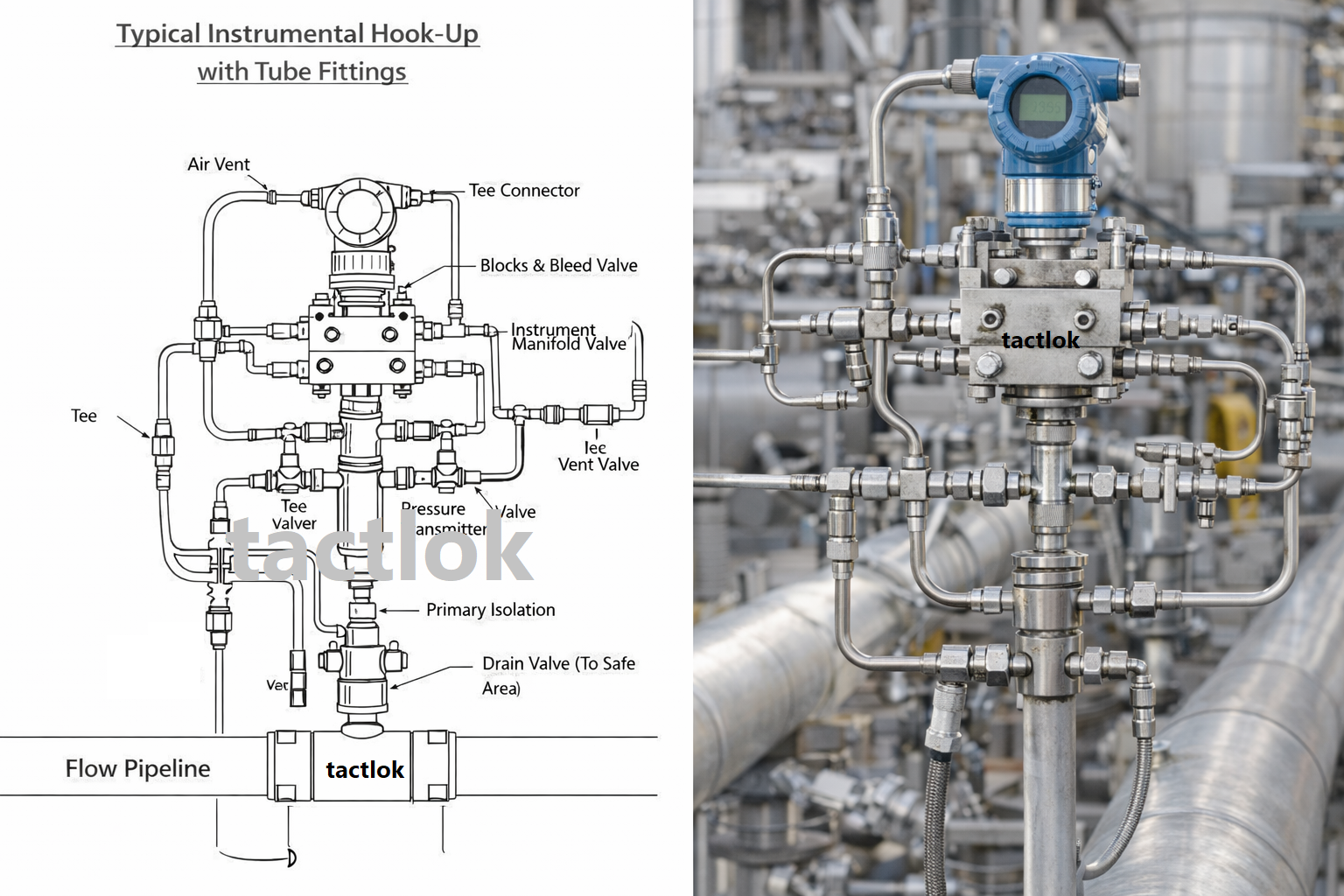
In process instrumentation, the “hook-up” refers to the complete assembly of components that connect a process instrument (transmitter, gauge, switch, etc.) to the process piping or vessel. This critical interface determines the accuracy, reliability, and longevity of your measurements. Samvay Fluid Tekniks Inc. offers a comprehensive range of instrument hook-up fittings—from the root valve at the process connection to the final instrument connection—all engineered to work together as a cohesive system.
What Are Instrument Hook-Up Fittings?
Instrument hook-up fittings encompass all components between the process tapping point and the instrument. A complete hook-up typically includes:
| Component | Function | Located |
|---|---|---|
| Root Valve | Primary isolation at process connection | At process tapping |
| Condensate Pot / Syphon | Protect instrument from steam/high temperature | Between root valve and manifold |
| Instrument Manifold | Isolation, equalization, vent/drain functions | Directly at instrument |
| Impulse Lines / Tubing | Connect process to instrument | Between root valve and instrument |
| Tube Fittings | Connect tubing to valves and instruments | Throughout the system |
| Valves (Block, Bleed, Calibration) | Additional isolation and test points | As required |
| Snubbers / Pulsation Dampeners | Smooth pressure fluctuations | Before instrument |
| Flange Connectors | Connect tubing to flanged equipment | Interface points |
| Mounting Brackets | Support and secure components | For panel or pipe mounting |
| Accessories | Tags, guards, insulation | As required |
Why Choose Samvay for Hook-Up Fittings?
| Advantage | Benefit |
|---|---|
| Complete System Solution | All components from one source—perfect compatibility |
| Material Consistency | Same material grades throughout the system |
| Full Traceability | Complete documentation for quality audits |
| Global Standards | ASME, ISO, NACE compliant |
Single Root Valves for Instrument Isolation
The root valve is the first isolation point from the process. Installed directly at the process tapping on pipes or vessels, it provides the ability to isolate the entire instrument hook-up for maintenance, calibration, or replacement without shutting down the process.
Product Overview
Single root valves are available in multiple configurations to suit different process conditions, mounting requirements, and operator preferences. They serve as the primary safety isolation point and must be robust, reliable, and accessible.
Types of Root Valves
| Valve Type | Operation | Best Application |
|---|---|---|
| Needle Valve | Multi-turn, precise control | General instrumentation, throttling not typically required |
| Ball Valve | Quarter-turn, quick shut-off | Where fast isolation is needed, high cycle life |
| Gate Valve | Multi-turn, full bore | Large bore, minimum pressure drop |
| OS&Y Valve | Outside screw and yoke | Visible indication of valve position |
Technical Specifications
| Specification | Details |
| Material of Construction | SS316/L, SS304/L, Carbon Steel (A105), Monel, Hastelloy, Duplex |
| Connection Type | Male NPT/BSP, Female NPT/BSP, Socket Weld, Butt Weld |
| Connection Size | 1/4″, 3/8″, 1/2″, 3/4″, 1″ |
| Pressure Rating | 3000 PSI (standard), 6000 PSI, 10,000 PSI (high-pressure) |
| Temperature Range | -65°F to 600°F (-54°C to 315°C) standard; High-temp to 1200°F available |
| Stem Type | Non-rotating hardened tip (needle valves); Blowout-proof stem (all) |
| Packing | PTFE (standard), Grafoil (high-temp), Viton, EPDM |
| Seat Material | Integral metal seat (standard); Soft seat optional |
| Handle | T-bar (standard), Wheel (optional), Locking (optional) |
| Testing | 100% hydrostatic and pneumatic tested |
| Certification | EN 10204 3.1 material certification |
Single Root Valve Range
By Connection Type:
| Type | Configuration | Typical Use |
|---|---|---|
| Male x Female | Male thread into process, female outlet to tubing | Direct mount to process tapping |
| Male x Male | Both ends male | For welding boss or socket |
| Female x Female | Both ends female | Between two male connections |
| Socket Weld | For welding directly to pipe | Permanent installations |
| Butt Weld | Beveled ends for butt welding | High-pressure, high-temp |
By Size:
| Valve Size | Process Connection | Tube Outlet | Flow Coefficient (Cv) |
|---|---|---|---|
| 1/4″ | 1/4″ NPT | 1/4″ tube fitting | 0.3-0.4 |
| 3/8″ | 3/8″ NPT | 3/8″ tube fitting | 0.6-0.8 |
| 1/2″ | 1/2″ NPT | 1/2″ tube fitting | 1.0-1.2 |
| 3/4″ | 3/4″ NPT | 3/4″ tube fitting | 1.8-2.2 |
| 1″ | 1″ NPT | 1″ tube fitting | 3.0-3.5 |
Industry Applications
| Industry | Typical Root Valve | Special Requirements |
|---|---|---|
| Oil & Gas Production | 1/2″ 6000 PSI needle valve | NACE MR0175 |
| Refineries | 1/2″ 3000 PSI ball valve | Fire-safe, high-temp |
| Chemical Plants | 1/2″ 3000 PSI needle valve | Corrosion-resistant alloy |
| Power Generation | 1/2″ 6000 PSI needle valve | High-temperature packing |
| Water Treatment | 1/2″ 3000 PSI ball valve | NSF/ANSI 61 (optional) |
| Pharmaceutical | 1/2″ sanitary diaphragm valve | Electropolished, USP |
Double Block & Bleed Root Valves for Critical Isolation
For applications requiring positive isolation—such as hazardous fluids, high-pressure systems, or when maintenance must be performed safely—double block and bleed (DBB) root valves provide two independent isolation barriers with a vent/bleed between them.
Product Overview
A double block and bleed valve consists of two isolation valves (blocks) in series with a bleed valve between them. When both block valves are closed, the bleed valve can be opened to verify that no pressure is trapped between them, confirming complete isolation from the process.
Key Features & Benefits
| Feature | Benefit |
|---|---|
| Two Independent Isolation Valves | Redundant sealing, fail-safe isolation |
| Integral Bleed Valve | Verify isolation, vent trapped pressure |
| Compact Design | One body, multiple functions—saves space |
| One-Piece Construction | No leak paths between valves |
| Pressure Indication Port | Optional gauge port for verification |
Technical Specifications
| Specification | Details |
| Material | SS316/L, SS304/L, Carbon Steel, Duplex |
| Pressure Rating | 3000 PSI, 6000 PSI, 10,000 PSI |
| Temperature | -65°F to 600°F (-54°C to 315°C) |
| Inlet Connection | 1/2″ NPT male (to process) |
| Outlet Connection | 1/2″ NPT female (to tubing) |
| Bleed Connection | 1/4″ NPT female |
| Block Valves | Needle or ball type |
| Bleed Valve | Needle type (for controlled venting) |
| Configuration | In-line or angle pattern |
| Testing | 100% hydrostatic, seat leakage tests |
Available Configurations
| Configuration | Block Valves | Bleed Location | Best For |
|---|---|---|---|
| In-line DBB | Both in line | Between blocks | Vertical pipe runs |
| Angle DBB | One at 90° | Between blocks | Space-limited areas |
| With Gauge Port | Both in line | Between blocks + gauge port | Local pressure indication |
| With Calibration Port | Both in line | Between blocks + test connection | Field calibration |
Industry Applications
| Application | Why DBB Required |
|---|---|
| Sour Gas Service | Positive isolation of H2S |
| High-Pressure Steam | Safety during maintenance |
| Toxic Chemicals | Prevent any leakage |
| Critical Safety Systems | Redundant isolation |
| Offshore Platforms | Space-saving, safety |
2-Valve Instrument Manifolds for DP Transmitters
The 2-valve manifold is the most common configuration for differential pressure (DP) transmitters. It provides two block valves—one for the high-pressure side and one for the low-pressure side—allowing isolation of the transmitter from the process.
Product Overview
A 2-valve manifold mounts directly to the DP transmitter or is installed in the impulse lines. With both block valves closed, the transmitter can be removed for maintenance. However, a 2-valve manifold does not provide equalization between high and low sides, so it is typically used for liquid service where the equalization function is not critical.
Key Features
| Feature | Benefit |
|---|---|
| Two Block Valves | Isolate transmitter from process |
| Direct Mount to Transmitter | Eliminates impulse lines, reduces leak points |
| Compact Design | Fits in tight spaces |
| Bleed Ports (Optional) | Vent/drain capabilities |
| Multiple Connection Options | NPT, flanged, or tube extensions |
Technical Specifications
| Specification | Details |
| Material | SS316/L (standard), SS304, Carbon Steel, Duplex, Hastelloy |
| Pressure Rating | 3000 PSI (standard), 6000 PSI, 10,000 PSI |
| Temperature | -65°F to 600°F (-54°C to 315°C) |
| Process Connections | 1/4″, 1/2″ NPT/Female |
| Transmitter Connection | 1/4″ NPT (standard), 1/2″ NPT, or as required |
| Bleed Connections | 1/4″ NPT (optional) |
| Mounting | Direct mount to transmitter or inline |
| Valve Type | Needle valves (standard), Ball valves (optional) |
| Packing | PTFE (standard), Grafoil (high-temp) |
2-Valve Manifold Types
| Type | Description | Application |
|---|---|---|
| Direct Mount | Bolts directly to transmitter | Most common, eliminates impulse lines |
| Inline | Mounts in impulse lines | Remote mount, space constraints |
| With Bleeds | Includes vent/drain ports | For liquid or gas with trapping concerns |
| Flanged | Flanged process connections | For mating to flanged impulse lines |
Installation Options
Direct Mounting (Rosemount Compatible):
- Standard bolt pattern fits most DP transmitters
- Gasket included for leak-free seal
- No additional piping required
Inline Mounting:
- 1/4″ or 1/2″ NPT connections
- Can be bracket-mounted
- Flexible installation locations
3-Valve Instrument Manifolds with Equalization
The 3-valve manifold is the most versatile and widely used configuration for differential pressure transmitters. It adds an equalization valve between the high and low pressure sides, allowing the transmitter to be zeroed and calibrated in place without removing it from service.
Product Overview
A 3-valve manifold consists of:
- High-Pressure Block Valve – Isolates HP side
- Low-Pressure Block Valve – Isolates LP side
- Equalization Valve – Connects HP and LP sides
The equalization valve allows the two sides of the transmitter to be connected together, equalizing pressure. This is essential for:
- Zero checks and calibration
- Steam service (to protect against thermal shock)
- Gas service (to prevent over-range during start-up)
Key Features
| Feature | Benefit |
|---|---|
| Two Block Valves + Equalizer | Complete control of transmitter |
| Direct Mount to Transmitter | Eliminates impulse lines, reduces leak points |
| In-Situ Calibration | Zero and span without removal |
| Steam Service Compatible | Prevents thermal shock during start-up |
| Bleed Ports (Optional) | Vent/drain capabilities |
| Multiple Handle Options | Standard T-bar, wheel, or locking |
Technical Specifications
| Specification | Details |
|---|---|
| Material | SS316/L (standard), SS304, Carbon Steel, Duplex, Hastelloy |
| Pressure Rating | 3000 PSI (standard), 6000 PSI, 10,000 PSI |
| Temperature | -65°F to 600°F (-54°C to 315°C); High-temp to 1200°F available |
| Process Connections | 1/4″, 1/2″ NPT/Female |
| Transmitter Connection | 1/4″ NPT (standard), 1/2″ NPT, or as required |
| Equalization Port | Internal within manifold body |
| Bleed Connections | 1/4″ NPT (optional) |
| Mounting | Direct mount to transmitter or inline |
| Valve Type | Needle valves (standard), Ball valves (optional) |
| Stem Packing | PTFE (standard), Grafoil (high-temp), Viton (chemical) |
3-Valve Manifold Types
By Mounting:
| Type | Description | Best For |
|---|---|---|
| Direct Mount | Bolts directly to transmitter (Rosemount, Yokogawa, etc.) | Most applications, eliminates impulse lines |
| Inline | Mounts in impulse lines | When direct mount not possible |
| Flanged | Flanged process connections | High-pressure, mating to flanged systems |
By Valve Arrangement:
| Arrangement | Block Valves | Equalizer | Typical Use |
|---|---|---|---|
| Standard | Both blocks on same side | Center | General purpose |
| Opposed | Blocks on opposite sides | Center | Space constraints |
| Angle Pattern | Valves at 90° | Center | Tight installations |
By Features:
| Feature | Description | Application |
|---|---|---|
| With Bleeds | Vent/drain ports on each side | Liquid service, trapping concerns |
| With Test Ports | Connections for calibration equipment | Frequent calibration |
| High-Temperature | Extended stem, Grafoil packing | Steam, hot process |
| Oxygen Clean | Special cleaning, no lubricants | Oxygen service |
Standard Bolt Patterns (Direct Mount)
| Transmitter Brand | Model Series | Bolt Spacing | Manifold Pattern |
|---|---|---|---|
| Rosemount | 3051, 2051 | 2-1/8″ (54mm) | Standard |
| Rosemount | 1151 | 2-1/8″ (54mm) | Standard |
| Yokogawa | EJA Series | 54mm | Standard (compatible) |
| Honeywell | ST 3000 | 54mm | Standard (compatible) |
| ABB | 2600T | 54mm | Standard (compatible) |
| Siemens | SITRANS P | 54mm | Standard (compatible) |
| Foxboro | I/A Series | 54mm | Standard (compatible) |
| Endress+Hauser | Cerabar, Deltabar | 54mm | Standard (compatible) |
Industry Applications
| Industry | Typical Manifold | Special Features |
|---|---|---|
| Oil & Gas Production | 3-valve, 6000 PSI | NACE MR0175, RTJ flange options |
| Refineries | 3-valve, 3000 PSI | High-temp packing, fire-safe |
| Chemical Plants | 3-valve, 3000 PSI | Hastelloy for corrosive, PTFE packing |
| Power Generation | 3-valve, 6000 PSI | High-temp, extended stem |
| Steam Service | 3-valve, 3000 PSI | Grafoil packing, condensate handling |
| Gas Processing | 3-valve, 6000 PSI | NACE, low-temp options |
| Pharmaceutical | Sanitary diaphragm manifold | Electropolished, USP |
5-Valve Instrument Manifolds for Maximum Control
For applications requiring the highest level of control and flexibility—such as custody transfer, critical safety systems, or when frequent calibration is needed—the 5-valve manifold adds vent/calibration valves to the standard 3-valve configuration.
Product Overview
A 5-valve manifold includes:
- High-Pressure Block Valve
- Low-Pressure Block Valve
- Equalization Valve
- High-Pressure Vent/Calibration Valve
- Low-Pressure Vent/Calibration Valve
The additional vent valves allow:
- Venting of trapped pressure on either side
- Connection of calibration equipment without disturbing process connections
- Drainage of condensate from each side
- Safe bleeding before disconnection
Key Features
| Feature | Benefit |
|---|---|
| All Functions in One Body | Complete control, minimal connections |
| Individual Side Vents | Vent/drain each side independently |
| Calibration Ports | Connect calibrator without disassembly |
| Positive Isolation | Double block available on each side |
| Compact Design | All functions in one compact package |
Technical Specifications
| Specification | Details |
|---|---|
| Material | SS316/L (standard), SS304, Carbon Steel, Duplex, Hastelloy |
| Pressure Rating | 3000 PSI (standard), 6000 PSI |
| Temperature | -65°F to 600°F (-54°C to 315°C) |
| Process Connections | 1/2″ NPT/Female (standard) |
| Transmitter Connection | 1/4″ or 1/2″ NPT |
| Vent Connections | 1/4″ NPT (standard) |
| Mounting | Direct mount to transmitter |
| Valve Type | Needle valves (all) |
| Handle Configuration | All handles on same side for easy access |
5-Valve Manifold Types
| Type | Configuration | Best For |
|---|---|---|
| Standard | All valves accessible from front | Panel mounting, easy access |
| Compact | Smaller footprint | Tight spaces |
| With Test Ports | Additional 1/4″ ports on vents | Frequent calibration |
Double Compression Tube Fittings for Instrumentation
The backbone of any instrument hook-up system is the tube fittings that connect all components together. Samvay’s double compression tube fittings use a two-ferrule system that provides independent sealing and gripping functions for reliable, leak-free connections.
Product Overview
Double compression (also called two-ferrule) tube fittings are the industry standard for instrumentation applications. The design separates the sealing and gripping functions:
- Front Ferrule: Seals on the tube and fitting body (creates leak-tight metal-to-metal seal)
- Back Ferrule: Grips the tube securely (acts as a spring, absorbs vibration)
This independent action ensures:
- No tube rotation during make-up (prevents scoring)
- Excellent vibration resistance
- Multiple remakes without performance loss
- Consistent, reliable sealing
Key Features
| Feature | Benefit |
|---|---|
| Two-Ferrule System | Independent sealing and gripping |
| No Tube Rotation | No scoring, ideal for thin-wall tubing |
| Vibration Resistant | Back ferrule absorbs movement |
| Reusable | Multiple assembly cycles |
| Wide Temperature Range | -425°F to 1200°F |
| Broad Pressure Range | Vacuum to 6000 PSI |
| Material Consistency | Same alloy throughout |
| Interchangeable | Industry-standard dimensions |
Technical Specifications
| Specification | Details |
|---|---|
| Material | SS316/L (standard), SS304, SS316Ti, SS321, Monel, Hastelloy, Inconel, Titanium |
| Tube Size Range | 1/8″, 3/16″, 1/4″, 5/16″, 3/8″, 1/2″, 5/8″, 3/4″, 1″ OD; Metric: 3mm to 25mm |
| Pressure Rating | Up to 6000 PSI (depending on size and material) |
| Temperature Rating | -425°F to 1200°F (-254°C to 649°C) |
| Thread Standards | NPT (ASME B1.20.1), BSP (ISO 228), Metric |
| Fitting Configurations | Straight, Elbow, Tee, Bulkhead, Union, Cross, etc. |
| Ferrule Material | Same as body (standard); Hardened available |
| Surface Finish | As-machined, passivated, electropolished |
| Testing | 100% pressure tested |
Complete Tube Fitting Range
Connectors:
| Type | Description | Typical Use |
|---|---|---|
| Straight Connector | Male/Female thread to tube | Connect tube to threaded port |
| Union | Tube to tube, straight | Extend tube runs |
| Reducing Union | Connect different tube sizes | Transition between sizes |
| Bulkhead Union | Through-panel connection | Panel feed-through |
| Swivel Connector | Rotatable thread | Orient fittings easily |
Elbows & Tees:
| Type | Description | Typical Use |
|---|---|---|
| 90° Elbow | Change direction | Corners, space constraints |
| 45° Elbow | Gentle direction change | Gradual turns |
| Tee | Three-way connection | Branch lines |
| Cross | Four-way connection | Manifold applications |
Special Purpose:
| Type | Description | Typical Use |
|---|---|---|
| Bulkhead Connector | Panel mount with thread | Through-panel connections |
| Port Connector | Direct to component | Valve and instrument ports |
| Plug | Seal unused ports | Future expansion |
| Cap | Seal tube end | Temporary closures |
| Ferrule Set | Replacement ferrules | Maintenance |
Tube Fitting Configurations
| Configuration | Sizes Available | Pressure Rating |
|---|---|---|
| Straight Thread Connector | All sizes | 6000 PSI |
| Straight Tube Union | All sizes | 6000 PSI |
| 90° Elbow | All sizes | 6000 PSI |
| 45° Elbow | All sizes | 6000 PSI |
| Tee (Equal) | All sizes | 6000 PSI |
| Tee (Reducing) | Selected sizes | 6000 PSI |
| Bulkhead Union | 1/8″ to 1/2″ | 6000 PSI |
| Bulkhead Connector | 1/8″ to 1/2″ | 6000 PSI |
| Swivel Elbow | 1/4″ to 1/2″ | 3000 PSI |
| Swivel Tee | 1/4″ to 1/2″ | 3000 PSI |
| Cross | 1/4″ to 1/2″ | 6000 PSI |
| Plug | All sizes | 6000 PSI |
| Cap | All sizes | 6000 PSI |
Tube to Pipe Adapters
Connect tubing to threaded pipe connections with Samvay’s tube-to-pipe adapters. These transition fittings combine a double compression tube fitting on one end with standard NPT or BSP pipe threads on the other.
Technical Specifications
| Specification | Details |
|---|---|
| Material | SS316/L, SS304/L |
| Tube End | Double compression fitting for 1/8″ to 1″ OD tube |
| Pipe End | Male or female NPT/BSP, 1/8″ to 1″ |
| Pressure Rating | 6000 PSI |
| Temperature | -425°F to 1200°F |
Available Configurations
| Type | Tube End | Pipe End | Application |
|---|---|---|---|
| Male Adapter | Tube fitting | Male NPT | Connect tube to female pipe port |
| Female Adapter | Tube fitting | Female NPT | Connect tube to male pipe thread |
| Bulkhead Adapter | Tube fitting | Male NPT with nut | Panel mount |
Stainless Steel Instrumentation Tubing
The connecting lines between components are critical to system performance. Samvay offers a full range of stainless steel instrumentation tubing in seamless and welded construction, annealed for easy bending and flaring.
Technical Specifications
| Specification | Details |
|---|---|
| Material | SS304/L, SS316/L, SS321, SS347 |
| Standard | ASTM A269 (welded & drawn), ASTM A213 (seamless) |
| Size Range | 1/8″ to 1″ OD (3mm to 25mm metric) |
| Wall Thickness | 0.028″ to 0.095″ (standard); Custom available |
| Temper | Annealed for bending |
| Lengths | 20 ft (6m) random, 20 ft cut lengths |
| Surface | Bright annealed, pickled, or electropolished |
| Testing | Hydrostatic, eddy current, or pneumatic |
| Certification | EN 10204 3.1 |
Tubing Selection Guide
| Tube Size OD | Wall Thickness | Working Pressure (SS316) | Bend Radius |
|---|---|---|---|
| 1/4″ | 0.035″ | 3000 PSI | 1″ |
| 1/4″ | 0.049″ | 5000 PSI | 1-1/4″ |
| 3/8″ | 0.035″ | 2000 PSI | 1-1/2″ |
| 3/8″ | 0.049″ | 3200 PSI | 1-3/4″ |
| 1/2″ | 0.035″ | 1400 PSI | 2″ |
| 1/2″ | 0.049″ | 2200 PSI | 2-1/4″ |
| 1/2″ | 0.065″ | 3200 PSI | 2-1/2″ |
| 3/4″ | 0.049″ | 1500 PSI | 3-1/2″ |
| 3/4″ | 0.065″ | 2100 PSI | 4″ |
| 1″ | 0.065″ | 1500 PSI | 5″ |
| 1″ | 0.083″ | 2000 PSI | 6″ |
Test & Calibration Valves
For systems requiring frequent calibration or sample points, dedicated test and calibration valves provide safe, convenient access without disturbing the main hook-up.
Product Range
| Type | Description | Application |
|---|---|---|
| Single Test Valve | One valve with quick-connect fitting | Simple test points |
| Double Block & Bleed | Two isolation valves with bleed | Positive isolation for calibration |
| Calibration Manifold | Multiple valves in one body | Frequent calibration points |
| Sample Valves | Needle valve for sampling | Process sampling |
Appendix: Hook-Up Components Quick Reference Table
| Component | Typical Sizes | Typical Pressure | Common Materials | Applications |
|---|---|---|---|---|
| Root Valve (Single) | 1/4″ – 1″ | 3000-6000 PSI | SS316, CS | General isolation |
| Root Valve (DBB) | 1/2″ | 3000-6000 PSI | SS316 | Critical isolation |
| 2-Valve Manifold | 1/4″ – 1/2″ | 3000-6000 PSI | SS316 | Liquid DP |
| 3-Valve Manifold | 1/4″ – 1/2″ | 3000-6000 PSI | SS316 | Steam, gas, general |
| 5-Valve Manifold | 1/2″ | 3000-6000 PSI | SS316 | Critical, calibration |
| Condensate Pot | 2″ – 6″ x 8-24″ | 3000 PSI | SS316, CS | Steam service |
| Syphon (Pigtail) | 1/4″ – 1/2″ | 3000-6000 PSI | SS316 | Steam gauge protection |
| Snubber | 1/4″ – 1/2″ | 6000 PSI | SS316 | Pulsation dampening |
| Tube Fitting | 1/8″ – 1″ | 6000 PSI | SS316 | All connections |
| Tubing | 1/4″ – 1″ | varies | SS316 | Impulse lines |
| Test Valve | 1/4″ | 6000 PSI | SS316 | Calibration points |
| Bleed Valve | 1/4″ | 6000 PSI | SS316 | Vent/drain |
| Mounting Bracket | various | N/A | SS304 | Support |
| Tube Clamp | 1/4″ – 1″ | N/A | SS304, Plastic | Tube support |